MS Book and Mineral Company
Geology and Mining History of the United States
Mining History Photographs, Illustrations and Diagrams 2
Place an Order
MS Book and Mineral Company
Mining History Photographs, Illustrations and Diagrams
These are provided for fun and educational purposes.
If you have photos or illustrations you would like to add, please contact me: msbooks@booksgeology.com
Here are some photographs of Joshua Hendy Stamp Mills, originally manufactured in San Francisco, as seen during the summer of 2009 somewhere in the Sierra Nevada Range.
The specific location of these is omitted to preserve its integrity. These photographs were donated. I did not ask what the location was.
Many historic items such as this are dismantled and parts are sold for souvenirs. Please kindly leave historic items in the field as you find them for others to find and enjoy.
If you find more historic items out there and are willing to share, please send me digital copies so I can add them to this page.
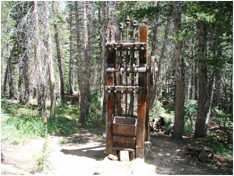
A Joshua Hendy 3 stamp mill
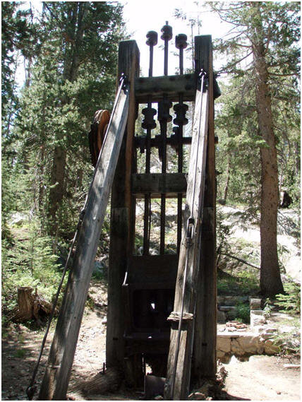
Rear view
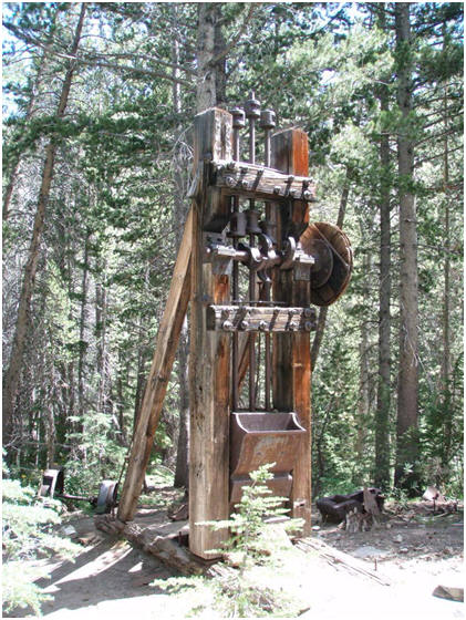
Front view
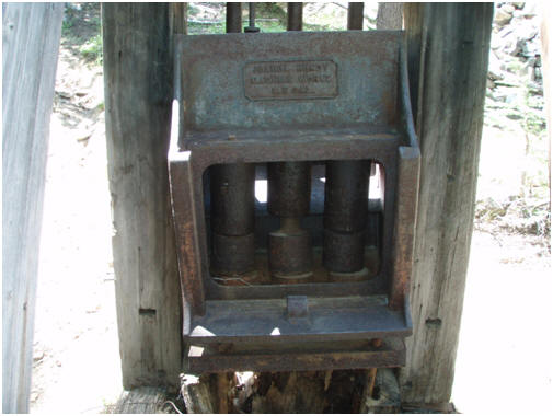
Close up of stamps
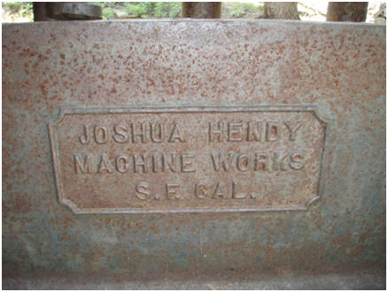
Detail of name plate
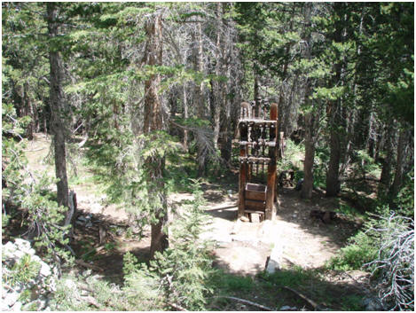
Distant view
Here are five illustrations of stamps mills produced in San Francisco by the Joshua Hendy Iron Works Company during the early 1900's.
The following illustrations came from a Joshua Hendy Catalog which I sold year ago.
I saved these illustrations from that catalog for everyone to see, study, and enjoy.
Can you identify the parts of a typical stamp mill? A key to the parts of a stamp mill is included below.
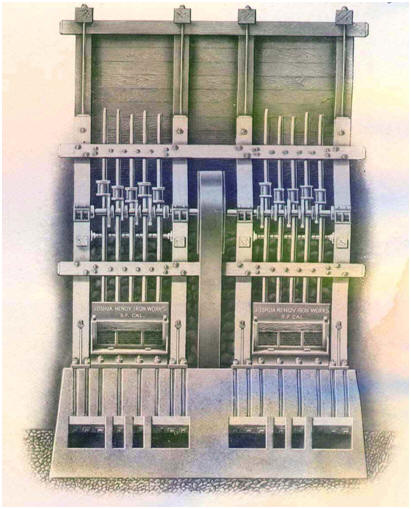
A Four Post Battery Frame
It was seldom used due to its increased overall height and cost over a three post stamp mill; the advantage of this stamp mill was it seldom had a broken camshaft
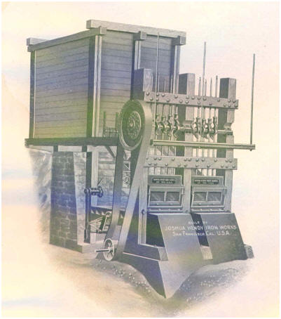
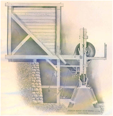
A 10-stamp mill mounted on concrete mortar blocks; the ore bin was
located to the rear
Stamps could be ordered from 850 pounds to 2,000 pounds each; stamps heavier than 850 pounds were not recommended for pack animal transportation
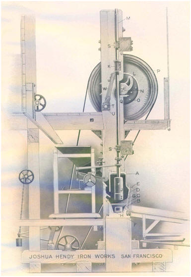
Cross-section of a standard battery frame with wood mortar blocks
Can you name the components of this stamp mill? (a key is provided
below)
The order of drop in a stamp mill
The most desirable order of drop was usually a 1 - 4 or a 1 - 5 drop.
The 1 - 4 drop was 1 - 4 - 2 - 5 - 3 meaning that stamp 1 dropped first, 4 was
second, 2 was third, 5 was fourth, and 3 was last. This drop was
also written as 1 - 3 - 5 - 2 - 4 which is the same, but written backwards.
This drop caused the ore to build up on an end of the mortar resulting
in an uneven distribution of labor on the dies.
The 1 - 5 drop was completed in the order 1 - 5 - 2 - 4 - 3 or written backwards,
1 - 4 - 2 - 3 - 5. The drop became the favorite as it gave the most
satisfactory results ever found.
The illustration here shows 10 stamps which commonly used the order
1 - 6 - 5 - 10 - 2 - 7 - 4 - 9 - 3 - 8.
Here is the key to the main components of a Joshua Hendy Stamp Mill as shown in the illustrations above:
A - mortar (this is the chamber inside the mill where the crushing and sometimes part of the amalgamation occurs; the walls of the mortar were usually made from cast iron, the exception was Gilpin County which used an iron base and the sides and ends being made from wood which made delivery in mountains terrame posible)
B - chuck or mortar block (were sometimes wooden for resilience, but usually were concrete for a solid foundation for constant pounding of the stamps; the Alaska Tredwell Company used cast iron anvils under mortar blocks for strength; the Gold King Mine in Colorado used a larger iron anvil blocks with a larger concrete base)
C - screen frame (these are the wood strips around the screens to hold them in place)
E - screen key (locks the screen in place)
F - rubber cushion (a layer under the shoe with some give; some did not have this)
G - screen (regulated the size of the crushed rock being turned out by the stamps)
H - dieI -
shoe or stamp head (the shoe crushes the ore; it is lifted by the the double armed cam; it drops when the full lift is reached; this cylindrical part was usually 8 to 10 inches in diameter and 6 to 10 inches high; it is surrounded by and secured by the shank which is wider at the top than at the base))J -
L - cam (consists of a circular hub and two projecting arms; the cam and the tappet must always be parallel to insure a minimum of jar and friction; the velocity of lift must be constant and the amount of lift must be proportional to the arc traversed by the camshaft; two-armed cams this arc must be less than 180o
Here is a diagram showing the position of a cam relative to a stem and tappet:

M - stem (this is the central shaft or spindle upon which the tappet, boss, and shoe are attached)
N -
camshaft (this is the metal shaft around which the cam rotates; it was made from the best metal available such as a chrome-nickel-steel combination; the best of these was forging down old propeller shafts from large steamshipsP -
drive pulley or bull wheel (these were made from several layers of wood held together by bolts and a cast iron hub with wide flanges; these varied in diameter from 6 to 8 feet and a width (thickness) of 12 to 18 inches; wood was used to absorb the vibration of cams striking the tappetsS -
guides (these kept the stems from deviating from their vertical path; some of these were made from wood and others were metal; multiple sets of guides were preferred)
Click any link to continue:
MS Book and Mineral Company
Geology and Mining History of the United States
Place an Order